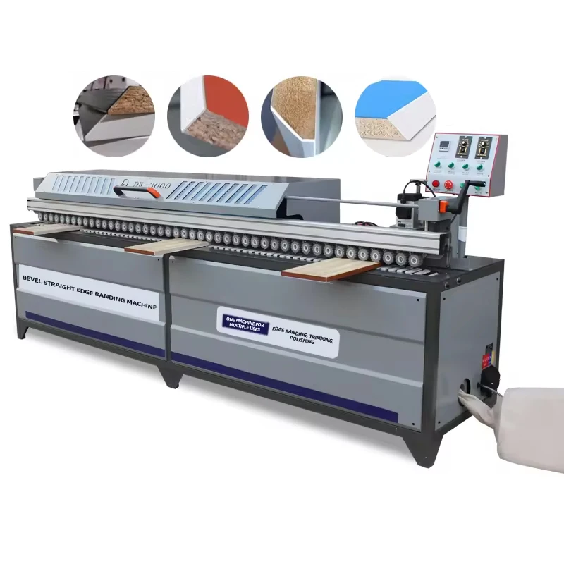
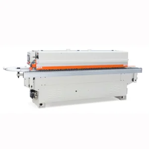
Verified Tolerance Mapping — every feed speed, motor rating, and pressure wheel angle on the DW3000 spec sheet traces back to a measurable station output before the machine leaves the factory floor.
Technical Specifications
| Parameter |
Value |
| Model |
DW3000 |
| Product Type |
45 Degree Oblique Straight Edge Banding Machine |
| Total Power |
11 kW |
| Voltage & Frequency |
380V / 415V (frequency to be confirmed per destination market) |
| Feed Speed |
0–12 m/min |
| Feed Power |
160 W |
| Transmission Power |
180 W |
| Pre-milling Motor |
2.2 kW |
| Heating Power |
2.2 kW × 2 (double heat gun) |
| Trimming Motors |
2.2 kW × 2 (spindle type) plus 800 W silent trimming motor |
| Polishing Power |
0.4 kW × 2 |
| Vacuum Power |
550 W |
| Glue Pot Capacity |
4000 ml |
| Edge Banding Height |
0–50 mm |
| Edge Banding Thickness |
0.3–3 mm |
| Minimum Sheet Length |
30 cm |
| Minimum Sheet Width |
15 cm |
| Oblique Pressure Wheels |
8 groups, adjustable 30–90° |
| Air Source Pressure |
0.5–0.7 MPa |
| Feeding Belt |
Double cylinder |
| Slotting Device |
Adjustable slotting height |
| Control Panel Language |
Chinese and English standard; Spanish and other languages available on request |
| Overall Dimensions (L × W × H) |
299 × 65 × 130 cm |
| Net Weight |
430 kg |
| Assembly State |
Fully automatic |
| Certification |
CE |
Application Suitability
| Application |
Material or Output |
| Custom cabinet door and carcass edge finishing |
MDF and particleboard with PVC or veneer banding |
| Plywood furniture panel edging |
Plywood panels up to 50 mm thickness with 0.3–3 mm edge strips |
| Angled and beveled edge profiles for decorative furniture |
Solid wood panels requiring 30–90° oblique banding |
| Small-batch joinery with mixed straight and bevel runs |
Mixed substrate batches transitioning between straight and 45° oblique profiles |
| Panel processing plants combining pre-milling, slotting, and polishing |
MDF, particleboard, plywood in a single automated pass |
Why Voltage Confirmation Must Precede the Purchase Order
A machine rated 380V/415V that arrives at a 220V three-phase site is a 430 kg paperweight until a transformer is sourced locally.
I once configured an oblique edge bander for a Middle East workshop, locked in the mechanical specs, and only later discovered the local grid ran a frequency and voltage combination the motor could not accept. The customer waited weeks for a step-up transformer while their production schedule collapsed. Every 45 degree oblique straight edge banding machine specifications sheet should be cross-referenced against the destination site's actual electrical infrastructure before production begins — not after the crate is sealed [NEED_CITE: voltage and frequency standards by export market].
The DW3000 ships configured for 380V or 415V, but frequency tolerance and phase balance at the installation site must be verified independently. A factory running on an unstable supply or a generator set may see the 2.2 kW pre-milling motor stall under load or the double heat guns fail to reach adhesive activation temperature. Confirming these parameters early eliminates the most common cause of commissioning delays.

Matching Feed Speed to Panel Thickness and Edge Profile
The 0–12 m/min variable feed speed on this 45 degree oblique straight edge banding machine is not a single optimal setting — it shifts depending on substrate density and banding thickness. Heavier MDF panels carrying 3 mm PVC edge strips demand a slower feed rate to allow the double heat guns sufficient dwell time for full adhesive activation. Thinner veneer banding on plywood, by contrast, can run closer to the upper feed limit without risking adhesion failure. The double cylinder feeding belt maintains consistent panel registration across this range, preventing the lateral drift that causes visible glue lines on lighter substrates.
Pressure Wheel Geometry and Edge Conformity Across Angles
The 8-group oblique pressure wheel system adjusts continuously between 30° and 90°, which matters when a single production run includes both straight-edged carcass panels and 45° beveled door components. Each wheel group applies independent contact pressure, so switching between profiles does not require mechanical recalibration of the entire pressure zone. This arrangement keeps edge conformity consistent whether the machine is pressing PVC into a straight rabbet or forcing veneer around a beveled contour, reducing the rework that typically follows profile changeovers [NEED_CITE: edge conformity tolerance standards for furniture panel assembly].
What the Motor Count Means for Downstream Assembly Quality
Three spindle trimming motors — two at 2.2 kW and one 800 W silent unit — handle different trimming passes across the panel edge. The higher-powered spindles remove bulk excess banding, while the flexible edge scraper cleans residual adhesive from the glue line before the 0.4 kW × 2 polishing wheels finish the surface. This station sequence directly affects whether panels pass or fail at the assembly bench: a trimming motor that leaves even a slight ridge causes misalignment when dowels or confirmat screws are driven. The pre-milling station at 2.2 kW squares the panel edge before banding enters the glue zone, which is where most tolerance stack-up originates in less complete machine configurations.
The Cost of Skipping Specification Verification
Buyers who select an edge bander on price alone and defer electrical and dimensional checks often face consequences that surface only during commissioning. A machine with insufficient glue pot capacity forces mid-run refills that interrupt heat stability. An air supply rated below 0.5 MPa causes the pressure wheels to lose contact force, producing the exact inconsistent glue lines the purchase was meant to eliminate. Panels processed on a machine whose minimum sheet dimensions do not match the actual offcut sizes in the shop result in jammed infeeds and damaged workpieces [NEED_CITE: common commissioning failure causes in panel edge banding equipment].
Procurement Verification Before Dispatch
Every DW3000 leaves the factory with a complete electrical schematic confirming the voltage and frequency configuration matched to your site's supply documentation. The four-stage quality control process includes an in-process check on pre-milling accuracy and a pre-shipment test that runs your specified panel thickness and edge banding material through every station. Multilingual control panels are configured before crating, so operators can read the interface from the first power-on. Spare parts lists and packing photographs are provided to support customs clearance and receiving inspection at your facility [NEED_CITE: CE machinery directive documentation requirements for exported woodworking equipment].
Documentation & Verification
- Machine specification sheet confirming all motor ratings, feed parameters, and dimensional data for the DW3000
- Electrical schematic with voltage and frequency confirmation matched to your factory supply
- Factory test record covering pre-milling tolerance and trimming finish on your specified panel material
- Operation and maintenance manual in the agreed language with illustrated station diagrams
- Spare parts list with part numbers for trimming motors, pressure wheels, and heating elements
- Packing photographs and customs documentation support for export clearance
Installation, Commissioning & Support
- Floor space allocation for the 299 × 65 × 130 cm footprint with clearance for panel infeed and outfeed
- Dedicated three-phase circuit rated for 11 kW total draw at the confirmed 380V or 415V supply
- Compressed air line delivering 0.5–0.7 MPa at the machine inlet with moisture filtration
- First-run parameter setup covering feed speed calibration, heat gun temperature, and pressure wheel angle
- Operator training on oblique angle adjustment and glue pot refill procedure for the 4000 ml capacity
- Scheduled maintenance intervals for spindle trimming motor bearings and feeding belt tension checks
What to Include With Your Inquiry
Send your typical panel materials and thickness range, the edge banding types you run (PVC, veneer, or both), and whether your production includes 45° bevel profiles alongside straight edges. Confirm your site voltage, frequency, and available compressed air capacity. If you have upstream panel sizing equipment or downstream assembly stations, note their throughput so the feed speed range can be matched to your line.
Frequently Asked Questions
Q: How is the 0–12 m/min feed speed calibrated, and does it vary by panel material?
A: Feed speed is adjustable across the full range via the control panel. Heavier substrates like high-density MDF with 3 mm PVC banding require slower feed rates to ensure the double heat guns fully activate the adhesive. Thinner veneer on plywood can run faster. The double cylinder feeding belt maintains panel stability regardless of speed setting.
Q: What is the difference between the standard 800 W trimming motor and the spindle trimming motor?
A: The 800 W silent trimming motor handles light finishing passes with reduced noise. The 2.2 kW spindle trimming motors perform heavier material removal on thicker PVC and solid wood banding. The DW3000 includes both types, allowing operators to select the appropriate motor for each edge profile without manual tool changes.
Q: Can the 380V/415V configuration be confirmed against my factory voltage before production?
A: Yes. The electrical schematic and voltage confirmation document are prepared before production begins, based on the grid parameters you provide. Frequency must also be specified, as motor winding and heat gun element ratings depend on both values. This verification step is mandatory in the sales process to prevent commissioning failures.
Q: What minimum panel dimensions does the machine accept?
A: The DW3000 accepts sheets with a minimum length of 30 cm and minimum width of 15 cm. These dimensions ensure the double cylinder feeding belt can maintain grip through all stations. Panels below these thresholds may not feed reliably and should be processed on a smaller-format machine.
Q: How is the 30–90° oblique pressure wheel angle set for different edge profiles?
A: Each of the 8 pressure wheel groups adjusts independently across the full 30–90° range. Operators set the angle via mechanical adjustment at the pressure zone, and the wheels maintain consistent contact force across the selected profile. This allows changeover between straight and beveled edges within a single production run without station recalibration.